
Spiral Wound Gaskets
Spiral Wound Gaskets
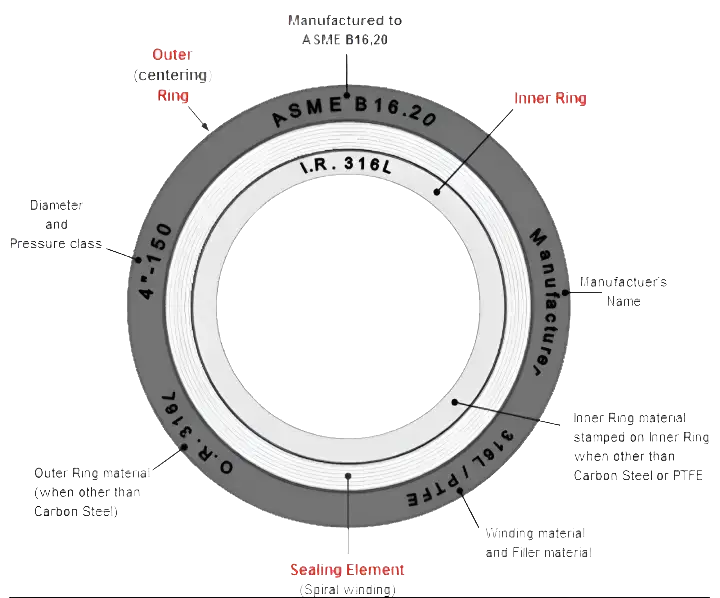
Spiral wound gaskets are widely used in the oil & gas industry, particularly in high operating pressure and critical applications. Spiral wound gaskets are manufactured by spirally winding a preformed metallic strip and a filler on the outer periphery of a metallic mandrel. The metal strip/metal wire (most often 304SS or 316SS) is wound outwards in a circle and the filler material (most often graphite) is wound starting at the opposite side in the same direction. This results in a growing circle of alternating layers of filler material and metal strip. The guide ring of a spiral wound gasket allows for the centering of the sealing element on the flange face, as well as delivers additional radial strength, and acts as a compression limiter. The outer metal ring of a spiral wound gasket holds the windings of the gasket in place and centers the gasket between the flange bolting, aligning the sealing surfaces. The finished product will resemble the spiral wound gasket image below, with the various components discussed here indicated with labels.
Inventory
First Distributors stocks the following gaskets and can often provide them same-day delivery. First Distributors can also provide spiral wound gaskets with larger diameters, as well as special alloys (Alloy 20, Monel, Hastelloy, Inconel, Titanium, etc), however these items may be subject to a longer lead time for delivery.
| Size Range: | ¼” to 36” Diameter |
| Class: | 150 – 2500 |
| Windings: | 304 SS, 316 SS |
| Filler: | Graphite, Teflon |
Ordering Information
There are some need to know details when purchasing spiral wound gaskets, such as, diameter, pressure rating, series A or B (above NPS 24”), whether there is an inner ring, if so, then material for the inner ring, winding, filler, and outer ring.
Pressure Class
Corresponding to flange pressure classes, spiral wound gaskets are available in 150, 300, 600, 900, 1500, and 2500 pressure classes. A low-pressure class (I.E. 150#) is made to a low-density construction, with a low number of metallic windings per unit width. High density applications require a more resilient design and a higher number of metallic windings per unit width must be incorporated into the gasket design. Therefore, data sheets do not exist to cover all variations of the spiral wound gasket design.
Material (Winding and Filler)
Material is identified by the color on the outer edge of the gasket. The stripe along the outer edge denotes filler (graphite, Teflon, etc.). The color chart below shows the different material colors for the outer edge and fillers that the gaskets identify by.
It is important to note that the sealing surface for a spiral wound gasket is only along the windings and filler. The outer ring is less thick than the windings, and therefore does not interact with the sealing surface of the flanges. The thickness of the windings is a standardized 1/8” thick, regardless the size of the gasket.
Inner Ring
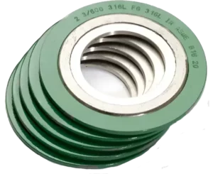
A spiral wound gasket with an inner ring is common because the inner ring helps prevent what is known as spooling. Spooling can be caused when pressure is applied during bolting, causing the winding to uncoil in the ID of the gasket, causing a lot of problems. This can also happen during the pigging process used when cleaning a pipeline.
Series A vs Series B
Large bore flanges (above NPS 24") to ASME B16.47-Serie A or MSS-SP 44 are heavier/stronger than the ASME B16.47-Series B in the same size and pressure rating. In most end-users piping specifications the Series A is specified, which can withstand more external loadings than the Series B type. For both series, the dimensions are different. From a commercial point of view, the series B type may be selected for piping with a non-critical application.
Dimensional Data
This chart shows the inner and outer diameter of spiral wound gaskets, where all dimensions are given in millimeters.
Gaskets according to ASME B16.21 (2011)
| NPS | d1 | d2 | ||||
|---|---|---|---|---|---|---|
| Class 150 | Class 300 | Class 400 | Class 600 | Class 900 | ||
| 1/2 | 21 | 48 | 54 | 54 | 54 | 64 |
| 3/4 | 27 | 57 | 67 | 67 | 67 | 70 |
| 1 | 33 | 67 | 73 | 73 | 73 | 79 |
| 11⁄4 | 42 | 76 | 83 | 83 | 83 | 89 |
| 11⁄2 | 48 | 86 | 95 | 95 | 95 | 98 |
| 2 | 60 | 105 | 111 | 111 | 111 | 143 |
| 21⁄2 | 73 | 124 | 130 | 130 | 130.2 | 165 |
| 3 | 89 | 137 | 149 | 149 | 149 | 168 |
| 31⁄2 | 102 | 162 | 165 | 162 | 162 | ... |
| 4 | 114 | 175 | 181 | 178 | 194 | 206 |
| 5 | 141 | 197 | 216 | 213 | 241 | 248 |
| 6 | 168 | 222 | 251 | 248 | 267 | 289 |
| 8 | 219 | 279 | 308 | 305 | 321 | 359 |
| 10 | 273 | 340 | 362 | 359 | 400 | 435 |
| 12 | 324 | 410 | 422 | 419 | 457 | 498 |
| 14 | 356 | 451 | 486 | 483 | 492 | 521 |
| 16 | 406 | 514 | 540 | 537 | 565 | 575 |
| 18 | 457 | 549 | 597 | 594 | 613 | 638 |
| 20 | 508 | 606 | 654 | 648 | 683 | 699 |
| 24 | 610 | 718 | 775 | 768 | 791 | 838 |
| NPS | d1 | Class 150 | Class 300 | Class 400 | Class 600 | Class 900 |
| d2 | ||||||
General notes:
- d1 = Inside diameter.
- d2 = Outside diameter.
- Dimensional tolerances outside diameter NPS 12 and smaller: +0 / -1.5 mm.
- Dimensional tolerances outside diameter NPS 14 and larger: +0 / -3.0 mm.
- Dimensional tolerances inside diameter NPS 12 and smaller: ± 1.5 mm.
- Dimensional tolerances inside diameter NPS 14 and larger: ± 3.0 mm.